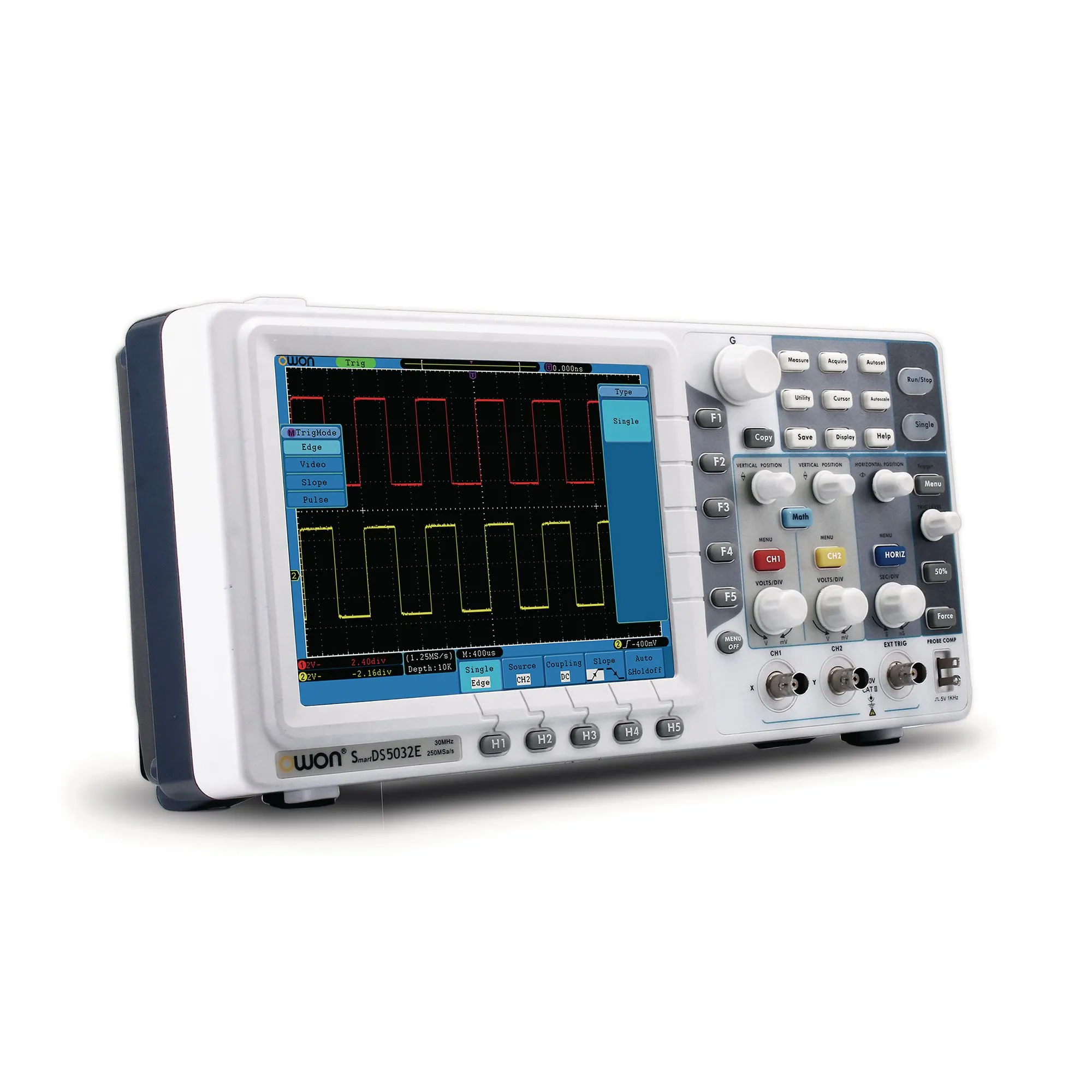
When it comes to using an oscilloscope, the probes are just as important as the instrument itself. They are the interface between the oscilloscope and the circuit you’re measuring. Selecting the right probe and learning how to use it properly can dramatically affect the accuracy of your measurements. This guide will help you navigate the various types of probes available, their specifications, and best practices for usage, ensuring that you get the most out of your measurements.
Understanding the Role of Oscilloscope Probes
What are Oscilloscope Probes?
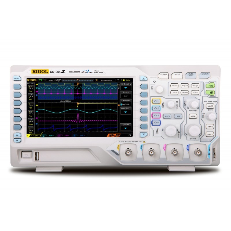
Oscilloscope probes are crucial accessories designed to connect your oscilloscope to the circuit being tested. They must deliver signals accurately to the oscilloscope while minimizing the alteration of the signal. Probes generally contain a small tip that makes contact with the circuit and can vary in types and specifications, each suited for different uses. Understanding their role will guide you in selecting the appropriate probe for your specific measurements.
Why Probes Matter
Probes directly influence the quality of your measurements. Using the wrong probe can lead to inaccurate readings, distorted waveforms, or damage to your oscilloscope or the circuit being tested. A well-chosen probe not only provides reliable data but also ensures that the oscilloscope functions optimally. By understanding the key features and types of probes available, you can make more informed choices, ultimately enhancing your projects and troubleshooting efforts.
Types of Oscilloscope Probes
Passive Probes
Passive probes are the most commonly used type of oscilloscope probe. These probes typically have resistive voltage dividers, which reduce the voltage signal to a level manageable by the oscilloscope. Passive probes usually have a bandwidth of up to 300 MHz, making them suitable for general-purpose applications. They are popular due to their simplicity, reliability, and affordability.
When using a passive probe, you can use either the x10 or x1 setting. The x10 setting reduces the input voltage, providing a larger dynamic range and minimizing loading effect on the circuit. This feature is particularly useful when measuring higher voltage signals. On the other hand, the x1 setting offers the actual voltage measurement without attenuation, but at the cost of more significant loading on the circuit.
Active Probes
Active probes contain internal amplification circuitry that ensures they maintain high signal fidelity, especially at higher frequencies. These probes are generally suitable for high-speed digital signals and applications that require precise measurements. Active probes can handle bandwidths exceeding 1 GHz, making them an excellent choice for advanced projects, such as RF (radio frequency) and high-speed digital designs.
Active probes require a power supply, which can be sourced from the oscilloscope itself or an external source. Note that while they provide better performance for fast signals, they tend to be more expensive than passive probes. For critical applications, the investment in an active probe often justifies the cost due to the increased accuracy and reduced noise.
Differential Probes
Differential probes are designed to measure the voltage difference between two points in a circuit without referencing ground. These probes are particularly useful in applications where common ground potentials can cause inaccuracies or where measuring floating signals is necessary. Differential probes help eliminate ground loops and minimize noise, delivering more accurate signal readings.
Most differential probes come with built-in isolation and can handle high voltages safely. When using differential probes, ensure they are rated for the specific application, paying attention to bandwidth and common mode rejection specifications. This type of probe is essential for advanced work in audio, RF, and mixed-signal circuits, providing flexibility in complex situations.
Key Specifications to Consider
Bandwidth
Bandwidth is a critical specification of any oscilloscope probe. It indicates the range of frequencies the probe can accurately measure. When selecting a probe, choose one with a bandwidth that meets or exceeds the frequency of your signals. As a general rule of thumb, the probe’s bandwidth should be at least three times greater than the frequency of the signal you are measuring to accurately capture all details of the waveform.
For example, if you work with signals around 100 MHz, look for probes with a bandwidth rating of at least 300 MHz. This bandwidth will ensure that the probe can accurately represent rapid transitions in the signal without distortion.
Attenuation
Attenuation refers to the reduction of signal amplitude that occurs when the signal travels through the probe. Most probes offer attenuation settings such as x1, x10, and x100. A higher attenuation setting allows you to measure higher voltage signals while protecting your oscilloscope from damage. For example, a x10 probe setting reduces the input voltage by a factor of ten, making it easier to safely capture larger signals.
Consider how much attenuation is necessary for the types of signals you will measure. If you anticipate frequently working with higher voltages, a probe that can provide high attenuation options will be essential to your setup.
Input Impedance
The input impedance of a probe defines how much it affects the circuit under test. High input impedance is essential to minimize loading effects, which can alter the signal being measured. Most passive probes have an input impedance of 1 MΩ with 10-15 pF capacitance, which is generally acceptable for most applications. However, if you’re working with sensitive circuits that require high fidelity, look for probes with a higher input impedance.
Active probes typically have higher input impedance, which makes them suitable for measuring high-frequency circuits without affecting their behavior. Understanding the input impedance helps you maintain the integrity of the signal you are observing.
Properly Connecting and Using Probes
Making the Connection
When connecting the probe to your circuit, ensure that the probe tip makes good contact with the measurement point. It’s important to consider the connection method that works best for the specific application; often, this can be a clip, hook, or spring-loaded tip. Proper grounding is equally crucial. If using a passive probe, connect the ground clip to the circuit’s ground point to avoid inaccurate measurements, which can lead to unexpected results.
Oscilloscope Settings
Before taking measurements, adjust your oscilloscope settings according to the probe type and expected signals. Set the vertical scale to an appropriate voltage level corresponding to the probe’s attenuation setting. If you are using a x10 probe, set the oscilloscope to recognize the attenuation to get accurate voltage readings.
After setting the vertical scale, adjust the timebase to get a clear view of the waveform. This typically involves setting the horizontal scale to match the frequency of the signal. These adjustments will help you visualize the waveform properly, facilitating accurate measurements and analysis.
Measuring Different Signal Types
AC vs. DC Signals
When measuring AC (alternating current) signals, set your oscilloscope to an appropriate coupling mode, typically AC coupling. AC coupling removes the DC component from the signal, allowing you to focus on the waveform undistorted by DC levels. This is particularly useful when analyzing signals that may contain a small AC signal riding on a larger DC component.
For DC (direct current) signals, use DC coupling to see the total voltage level without any filtering. This setting allows you to measure both AC and DC components accurately. Familiarize yourself with switching between these modes, as it can significantly impact the accuracy of your measurements.
Digital Signals
When measuring digital signals, ensure your probe’s bandwidth is sufficient to capture fast transitions and signal edges. For digital applications, using a scope with a higher sample rate ensures a more accurate depiction of the signal. If you’re working with digital circuits and want to analyze fast-switching states, consider using differential probes if the ground reference presents complications.
Different types of digital signals may require different probing techniques. For example, in a logic circuit, it might be beneficial to observe multiple points simultaneously to compare timings accurately across the system.
Maintenance and Care for Probes
Regular Inspection
Maintaining your probes is essential to ensure their longevity and accurate performance. Inspect probes regularly for any signs of wear or damage on the cables or connectors. Bent tips can affect measurements, while frayed wires can result in inaccurate readings. Make it a habit to check the integrity of your probes before use, ensuring they are ready for accurate measurements.
Proper Storage
When not in use, store probes in appropriate protective cases to prevent damage. Many oscilloscopes come with probe storage slots, but if not, keep them in a padded case or designated drawer. Avoid coiling the cables too tightly, as this can cause internal damage over time.
Cleaning the Probes
Periodically clean the probe tips, especially if they come into contact with solder or flux. Use a soft cloth dampened with isopropyl alcohol to gently clean the metal ends. Keeping them free from contaminants ensures better signal integrity and reduces wear and tear.
Troubleshooting Common Probe Issues
Signal Distortion
If you notice distorted signals while measuring, check for improper grounding or a damaged probe. Ensure that your probe’s connection is secure and that it is making adequate contact with the circuit. Verify that the oscilloscope settings correspond with the probe type and attenuation. Misconfigured settings can also lead to inaccurate or unclear displays.
Unexpected Noise
Noise could originate from the probe itself or the environment. If you’re experiencing excessive noise while using a probe, try switching to a coaxial probe or a differential probe if your application allows. Coaxial probes help minimize interference from external sources. Additionally, keeping probes away from high-frequency signals or switching power supplies can reduce unwanted noise.
Inaccurate Measurements
If your readings seem incorrect, verify probe settings, including attenuation and input impedance. A mismatch here can yield erroneous results. Also, check connections and ensure that the oscilloscope display is correctly calibrated. Regular calibration of the oscilloscope itself—along with probe checks—ensures that you get the most accurate data possible.
Conclusion
Choosing the right oscilloscope probes and understanding how to use them effectively is crucial for making accurate and reliable measurements. From selecting passive, active, or differential probes to adjusting settings for different signal types, every decision counts in obtaining precise readings. Regular maintenance and proper techniques ensure that your probes remain effective day in and day out.
By following the guidelines outlined in this article, you will build a solid foundation for using oscilloscope probes, facilitating accurate analysis in your electronic projects. With practice, you will gain confidence in troubleshooting circuits, measuring signals, and optimizing designs. Enjoy your journey into the world of oscilloscopes, and embrace the valuable insights these tools provide!
